We use cookies to help us deliver and improve this site. By clicking Confirm or by continuing to use the site, you agree to our use of cookies. For more information see our Cookie Policy.
Useful information on pump alignment
What is Pump Alignment?
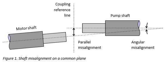
The transmission of power from a motor to a pump is achieved by connecting the motor shaft to the pump shaft, either directly or through a coupling of some type. Misalignment can occur in three ways:
- Radial (offset or parallel) misalignment
The centrelines of the two shafts are parallel but offset. - Axial (or end float) misalignment
The two shafts are aligned but one (or both) axles are prone to in/out movement along the centreline. - Angular misalignment
The centrelines of the two shafts are not parallel.
If these problems are not corrected, a system may suffer from a number of problems including the early failure of the pump or motor. Shaft misalignment can cause premature wear of a pump’s seal, packing, shaft, and bearings. This can then lead to excessive leakage and the system as a whole may exhibit excessive vibration and noise, reduced efficiency, and increased power and maintenance costs.
Centrifugal pumps used in petrochemical, chemical and refinery applications are regularly checked for alignment during installation, at frequent intervals during operation, and after service and maintenance.
How are Pumps and Motors Secured?
To maintain good alignment, it is important to minimise vibrations by securing the pumping system to sound foundations. Industrial pumps are normally bolted directly to a machined baseplate and other equipment is aligned and secured to it. The entire assembly is sited on a concrete foundation and affixed with epoxy or cement grouting. When constructed properly, overall vibrations can be substantially reduced because of the damping effect of the foundation mass. As a general rule, foundations should be at least three times the mass of the pumping system for centrifugal pumps and five times for reciprocating pumps.
When Should Alignment be Checked?
Manufacturers normally carry out a preliminary alignment test prior to installation. Positioning of the system on its foundation, and then grouting and the connection of piping may introduce unwanted stresses which affect the alignment. Further, during the early days of operation, thermal expansion and contraction can also cause movement in the bearings which affects alignment.
Alignment should therefore be checked carefully and repeatedly throughout installation, during the early days of operation, following maintenance or repairs, and scheduled periodically. Shaft alignment should also be monitored during the connection of any pipework. All components must be supported and introduce no stresses or strains on any other parts of the system.
If the system operates at temperature, alignment should be checked with the system filled with liquid and, if appropriate, at temperature because of the likelihood of thermal expansion.
What is Thermal Growth?
During operation at temperature, expansion of the drive shaft and other pump components can affect a pump’s alignment. This effect is called thermal growth and must be taken into account when selecting and fitting a shaft coupling and when correcting shaft alignment.
How is Alignment Measured?
For horizontal pumping systems, there are two main components to alignment:
- Parallel misalignment
The perpendicular horizontal misalignment between the two shafts’ centre lines - Angular misalignment
The angle between the two shafts' centre lines
Alignment is essentially based on measuring accurately the position of motor and pump shafts at two points or more. Various devices are available for measuring alignment offsets: feeler gauges, callipers, dial indicators and laser alignment tools.
Dial indicators measure relative position with a spring-loaded plunger which moves the dial needle when it is pushed in or let out. The plunger is fully extended if no pressure is applied to it and has a total travel of a few millimetres. The tool is held in place on a pump shaft by a clamp and jig system.
A laser shaft alignment tool performs measurements by means of two sensors mounted on two connected shafts. The sensors fire and receive laser beams from each other simultaneously to show whether the shafts are aligned within a certain tolerance.
Although laser alignment tools are easier to use and interpret, there are some environments in which the entirely mechanical dial indicators are preferred.
For vertical pumping systems, alignment is measured in two planes at 90° to each other.
How are Shafts Aligned?
For horizontal systems, the process is carried out in two stages:
- Vertical positioning
- Horizontal positioning
Normally, a pump is fixed to its base and this is secured to a rigid foundation. It is the drive motor shaft that is then aligned to the pump shaft. For vertical positioning, the motor has to be lifted safely in a controlled manner so that shims can be placed under the feet. This can be achieved in a variety of ways. Often, motors have integral jackscrews threaded vertically in all feet. These can allow sensitive height adjustment but can be prone to rusting or binding. Jacks or hydraulic wedges are available in a variety of types and load ratings. Cranes and hoists can also be used but are inconvenient.
For horizontal adjustments, it is common to use hammers (soft face, no-bounce or hollow) to nudge motors into position on their mountings. This requires reasonable access, does not offer great control and may cause damage. Some motors feature horizontal jackscrews and these allow fine adjustments but can be prone to rusting and sticking. These can also interfere with the positioning of shims.
Portable alignment positioners simplify the entire process including vertical, horizontal transverse and horizontal axial movements but are only cost effective for larger systems.
What is a Shim?
Shims are small discs or plates used to correct vertical positioning. Baseplates are normally machined so that a number of shims are required under a motor. Following measurement of the misalignment of the pump and motor shafts, shims are added to (or removed from) the motor’s feet to correct the vertical offset and angularity. Shims can be bought commercially in a range of sizes and thicknesses or can be homemade, as required. Slots may be required to accommodate integral jackscrews or lock-down bolts.
What is Soft Foot?
If a foot no longer makes good contact with the baseplate, a rocking motion, termed soft foot, may be the result and this will affect alignment measurements. Soft foot can arise from an uneven foundation or baseplate, or twisted or damaged feet on the motor or pump. It can also occur when multiple shims are placed under one or more feet to correct vertical alignment.
Soft foot affects shaft alignment measurements and can be a cause of noise and vibration. It is important to correct soft foot problems before tackling shaft alignment issues.
How are Shafts Connected?
Mechanical couplings are the most commonly used shaft connectors. These can be either rigid or flexible designs. Rigid couplings are generally used on vertical pumps; most horizontal pumps use flexible couplings. The latter can be either metallic or elastomeric. Elastomeric couplings are not suitable for use at high temperatures or in some chemical environments where they may be subject to degradation. Similarly, metallic couplings may not be suitable for use if they are exposed to corrosive substances.
Couplings, particularly flexible designs, accommodate some degree of shaft misalignment. They are normally rated for maximum permissible angular and parallel offsets. This advantage should not be an excuse to neglect shaft alignment. Any misalignment can cause damage to the pump, motor and, indeed, the coupling. However, some flexible couplings rely on lubricated, sliding components to accommodate misalignment and actually operate less efficiently with correctly aligned shafts. This is because some movement is necessary to maintain lubrication.
How can Misalignment Problems be Detected?
Noise and vibrations can be the first indications of problems with a running pumping system. Vibrational analysis, performed as part of a preventative maintenance and monitoring programme, can identify if shaft misalignment is becoming a problem. The diagnosis for shaft misalignment is indicated by abnormally high vibration levels at one and/or two times the shaft rotational rate frequency. Rapid identification of misalignment in this way can save a pumping system from damage.
Summary
Power is transmitted from a motor to a pump by connecting the motor shaft to the pump shaft, either directly or through a coupling. Systems should be checked for shaft alignment during installation, at frequent intervals during operation, and after service and maintenance. Misalignment can cause premature wear of a pump’s seal, packing, shaft, and bearings (leading to excessive leakage), and cause vibration, noise, reduced efficiency, and increased power and maintenance costs. Couplings, particularly flexible designs, allow some degree of shaft misalignment.
A number of devices are available for measuring alignment offsets including dial indicators and laser alignment tools. Vertical positioning adjustments involve the insertion of shims under the feet of a motor or pump, taking care to maintain good contact with the base. For large systems, portable alignment positioners may be cost effective.