We use cookies to help us deliver and improve this site. By clicking Confirm or by continuing to use the site, you agree to our use of cookies. For more information see our Cookie Policy.
Useful information on pump cavitation
What is cavitation?
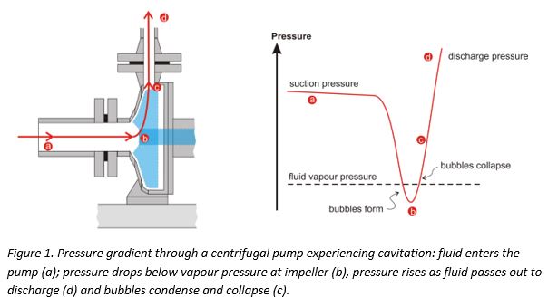
Across any pumping system there is a complex pressure profile. This arises from many properties of the system: the throughput rate, head pressure, friction losses both inside the pump and across the system as a whole. In a centrifugal pump, for example, there is a large drop in pressure at the impeller’s eye and an increase within its vanes (see Figure 1). In a positive displacement pump, the fluid’s pressure drops when it is drawn, essentially from rest, into the pumping chamber. The fluid’s pressure increases again when it is expelled.
If the pressure of the fluid at any point in a pump is lower than its vapour pressure, it will literally boil, forming vapour bubbles within the pump. The formation of bubbles leads to a loss in throughput and increased vibration and noise. However, when the bubbles pass on into a section of the pump at higher pressure, the vapour condenses and the bubbles implode, releasing, locally, damaging amounts of energy. This can cause severe erosion of pump components.
To avoid cavitation, it is important to match your pump to the fluid, system and application. This is a complex area and you are advised to discuss your application with the pump supplier.
What are the symptoms of cavitation?
The obvious symptoms of cavitation are noise and vibration. When bubbles of vapour implode they can make a series of bubbling, crackling, sounds as if gravel is rattling around the pump housing or pipework. In addition to the noise, there may be unusual vibrations not normally experienced when operating the pump and its associated equipment.
With centrifugal pumps, the discharge pressure will be reduced from that normally observed or predicted by the pump manufacturer. In positive displacement pumps, cavitation causes a reduction in flow rather than head or pressure because vapour bubbles displace fluid from the pumping chamber reducing its capacity.
Power consumption may also be affected under the erratic conditions associated with cavitation. It may fluctuate and will be higher to achieve the same throughput. Also, in extreme cases, when cavitation is damaging pump components, you may observe debris in the discharged liquid from pump components including seals and bearings.
How does cavitation cause damage?
Under the conditions favouring cavitation, vapour bubbles are seeded by surface defects on metal components within the pump: for example, the impeller of a centrifugal pump or the piston or gear of a positive displacement pump. When the bubbles are subjected to higher pressures at discharge they implode energetically, directing intense and highly focussed shockwaves, as high as 10,000MPa, at the metal surface on which the bubbles had nucleated. Since the bubbles preferentially form on tiny imperfections, more erosion occurs at these points.
When a pump is new, it is more resistant to cavitation because the metal components have few surface imperfections to seed bubble formation. There may be a period of operation before any damage occurs but, eventually, as surface defects accumulate, cavitation damage will become increasingly apparent.

What is ‘classic’ cavitation?
Classic (or classical) cavitation occurs when a pump is essentially starved of fluid (it is also called vaporization cavitation and inadequate NPSH-A cavitation). This can occur because of clogged filters, narrow upstream pipework or restricting (perhaps partially closed) valves. If the pump is fed from a tank, the level of liquid (or pressure above it) may have fallen below a critical level.
In a centrifugal pump, ‘classic’ cavitation occurs at the eye of the impeller as it imparts velocity on the liquid (see Figure 1). In a positive displacement pump, it can happen in an expanding piston, plunger or suction-side chamber in a gear pump. Reciprocating pumps, for example, should not be used in self-priming applications without careful evaluation of the operating conditions. During the suction phase, the pump chamber could fill completely with vapour, which then condenses in a shockwave during the compression phase.
What is Vane Passing Syndrome?
Vane Passing Syndrome, also known as vane syndrome, is a type of cavitation that occurs when the spacing between the vanes of a centrifugal pump’s impeller and its housing is too small, leading to turbulent and restricted flow and frictional heating. The pumped liquid expands as it passes beyond the constriction and cavitation occurs.
What is Suction Recirculation?
Suction recirculation (also called internal recirculation) is a potential problem observed with centrifugal pumps when operated at reduced flow rate. This might occur, for example, when a discharge valve has been left partially closed or when the pump is being operated at a flow below the minimum recommended by the pump manufacturer. Under these conditions, liquid may be ejected from the vanes back towards the suction pipe rather than up the discharge port. This causes turbulence and pressure pulses throughout the pump which may lead to intense cavitation.
What is Air Aspiration Cavitation?
Air can be sucked into a pumping system through leaking valves or other fittings and carried along, dissolved in the liquid. Air bubbles may form within the pump on the suction side, collapsing again with the higher pressure on the discharge side. This can create shock waves through the pump.
This type of cavitation can be prevented by regularly checking all valves and joints, O-rings and mechanical seals for signs of leaks or erosion.
What is NPSH?
To avoid cavitation, the pressure of the fluid must be maintained above its vapour pressure at all points as it passes through the pump. Manufacturers of centrifugal pumps specify a property referred to as the Net Positive Suction Head Required or NPSH-R – this is the minimum recommended fluid inlet pressure. The documentation supplied with your pump may contain charts showing how NPSH-R varies with flow.
In fact, NPSH-R is defined as the suction-side pressure at which cavitation reduces the discharge pressure by 3%: a pump is already experiencing cavitation at this pressure. Consequently, it is important to build in a safety margin (about 0.5 to 1m) to take account of this and other factors such as:
- The pump’s operating temperature
- Changes in atmospheric pressure
- Any increases in friction losses that may occur occasionally or gradually during the lifetime of the system.
So, in designing the suction-side pipework for your system, you must ensure that it exceeds the manufacturer’s NPSH-R rating for the operating conditions. Your calculated value is termed the NPSH-Available (NPSH-A).
How is NPSH-A calculated?
NPSH-A is calculated as the head or height of all the pressure contributions in the system:
NPSH-A = (Pe – Pv).10.2 + Hz – Hf + V².
ρ 2g
where:
- Pe = Absolute pressure in pumped vessel (bar)
- Pv = Vapour pressure of fluid (bar)
- ρe = Density of fluid (kg/dm³)
- Hz = Minimum fluid level above pump (m) (negative term if below pump)
- Hf = Friction losses in suction side pipework (m)
- Ve = Fluid velocity in pump flange (m/s)
- g = Acceleration due to gravity (9.81m/s²)
To avoid cavitation, always ensure that:
NPSH-A ³ NPSH-R + 0.5m
What is NPIP?
Positive displacement pumps require an inlet pressure to be a certain differential greater than the vapour pressure of the fluid to avoid cavitation during the suction phase. This is discussed in terms of Net Positive Inlet Pressure (NPIP) in a similar manner to NPSH for centrifugal pumps. NPSH is measured in feet or meters and NPIP is measured in pressure such as psi or bar. When converted to the same units, NPSH and NPIP are the same. Manufacturers may quote NPIP-R as the recommended inlet pressure and provide charts showing how it varies with pump speed. The available or actual inlet pressure on an operating system is termed NPIP-A.
Summary
Cavitation is a potentially damaging effect that occurs when the pressure of a liquid drops below its saturated vapour pressure. Under these conditions it forms bubbles of vapour within the fluid. If the pressure is increased again, the bubbles implode, releasing damaging shockwaves. This can cause severe erosion of components. A common example of cavitation is when a centrifugal pump is starved of feed: vapour bubbles form in the eye of the impeller as it imparts velocity on the liquid and collapse again on the discharge side of the vanes as the fluid pressure increases. This can lead to damage to an impeller’s vanes, seal or bearing. Cavitation can also occur in positive displacement pumps such as gear pumps and plunger pumps.
There are a number of measures that can be taken to reduce the risk of cavitation:
- Choose pumps carefully by consulting pump manufacturers and suppliers, discussing your application in detail.
- With a centrifugal pump, ensure that NPSH-A is at least 0.5m greater than NPSH-R during operation. For example, if the pump is fed from a tank, ensure that the level of liquid in the tank (or pressure above it) is sufficient. For a positive displacement pump, make sure that the inlet pressure complies with the manufacturer’s NPIP requirements.
- Lower the temperature of the liquid at the pump intake.
- Reduce pump speed.
- Clean suction-side filters regularly to ensure that the flow is not restricted by blockages.
- Regularly check seals, joints and valves for leaks and wear.
- Choose pump materials that are resistant to cavitation damage.
More info on our pump ranges |
|---|
Send us your enquiry |
Contact us |