We use cookies to help us deliver and improve this site. By clicking Confirm or by continuing to use the site, you agree to our use of cookies. For more information see our Cookie Policy.
Useful information on magnetic drive pumps
What are magnetic drive pumps?
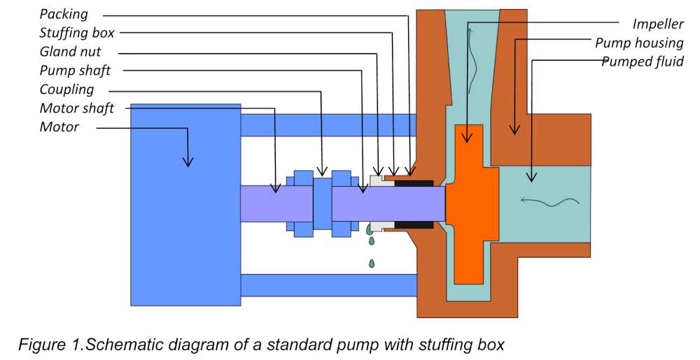
In a standard centrifugal pump, the drive shaft from the motor is connected, normally via a flexible coupling, to the impeller through the pump housing. This necessitates some form of seal where the drive shaft enters the housing (Figure 1).
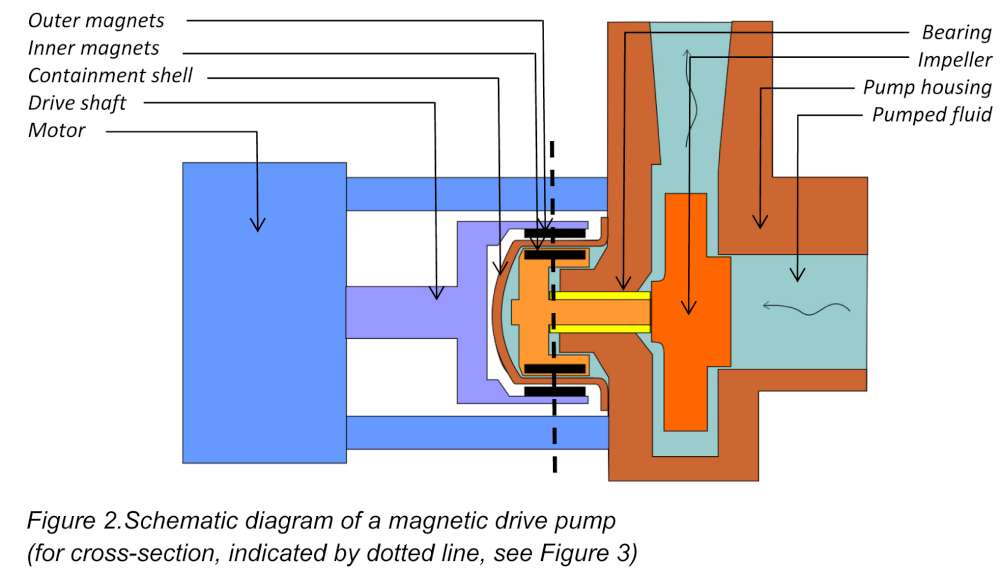
In a magnetic drive centrifugal pump, the impeller and the pumped fluid are contained within a hermetically sealed housing. The drive shaft from the motor rotates an assembly of magnets on the outside of the housing. Opposing this, on the inside of the housing, is a matching ring of magnets on a shaft attached to the impeller (Figure 2). Torque is transferred through the housing as a result of the coupled magnets.
There are also magnetic drive positive displacement pumps, vane pumps, internal gear pumps, and external gear pumps and the basic principles and advantages are the same: the pumped fluid is contained within a sealed housing eliminating the risk of leakage. For the purposes of this article, we shall continue to describe magnetic drives in the context of centrifugal pump design.
Why are magnetic drive pumps used?
With a standard centrifugal pump, some form of seal is necessary to stop the pumped medium from leaking out around the pump shaft, especially if it is at high pressure. There are three main options:
-
A soft packing material compressed around the pump shaft in a ‘stuffing box’ Packing material is held in place within the opening in the casing (the stuffing box) and compressed by a gland nut which can be progressively tightened as the packing material wears or settles (Figure 1).
-
Lip seal or O-ring
A rubber or plastic ring fits around the drive shaft and is held in place in a recess in the pump housing. -
Mechanical seal
A mechanical seal consists of two parts: a stationary component attached to the pump housing and a rotating component on the pump shaft. The faces of the two components are machined to be flat and smooth and are spring-loaded to keep them pressed together. This is the most effective option for reducing leaks but can be expensive and difficult to set up.
Leakage cannot be eliminated completely with any of these solutions and, in fact, it is important to maintain a small leakage to lubricate and cool the seal and pump shaft. In some cases, it is necessary to inject a lubricant to avoid overheating and this introduces the possibility of contamination of the pumped fluid.
A pump seal requires monitoring and frequent maintenance to avoid excessive leakage, particularly when the pumped fluid contains abrasives. All leaked fluids have to be contained and disposed of safely. If the fluid is also toxic, flammable, radioactive or environmentally damaging, the possibility of leaks, even minor ones, can be extremely dangerous. Leakages are one of the main causes of pump failures or shutdowns and the maintenance of seals and packing materials is expensive and time-consuming.
Environmental concerns and legislation has driven industry to implement cleaner pumping technology. A magnetic drive pump contains the pumped fluid completely within the pump housing. It only has a hermetic seal – a stationary gasket or O-ring - that is not subject to wear from moving parts and is therefore ideally suited to applications where no leakage can be tolerated either on safety grounds or because the costs of recovery and treatment are prohibitive.
How do magnetic drive pumps work?
The coupled magnets are attached to two concentric rings on either side of the containment shell on the pump housing (Figures2&3). The outer ring is attached to the motor’s drive shaft; the inner ring to the driven shaft of the impeller. Each ring contains about the same number of identical, matched and opposing magnets, arranged with alternating poles around each ring. The magnets are often made of rare earth metals such as samarium or neodymium alloyed with other metals. The most common combinations are Samarium-Cobalt and Neodymium-Iron-Boron. These complex alloys have two main advantages over traditional magnets:
-
Lower mass required to maintain a specific torque – hence smaller and less complex pumps.
-
Greater temperature stability – magnetic torque reduces with increases in temperatures but less so with rare earth alloy magnets than with traditional iron magnets
The use of these materials is a major factor in the cost of magnetic drive pumps. Most rare earth metals are mined in only a few places around the World (notably China) and prices can be volatile. For example, China manufactures 76% of the World’s Neodymium magnets. Apart from their cost, another disadvantage of these alloys is their poor resistance to corrosion. It is necessary to coat the magnets on the inner ring (which are exposed to the pumped fluid) with some form of protective resin or enclose them in a corrosion resistant casing, for example polypropylene, PVDF (polyvinylidene fluoride), ETFE or stainless steel.
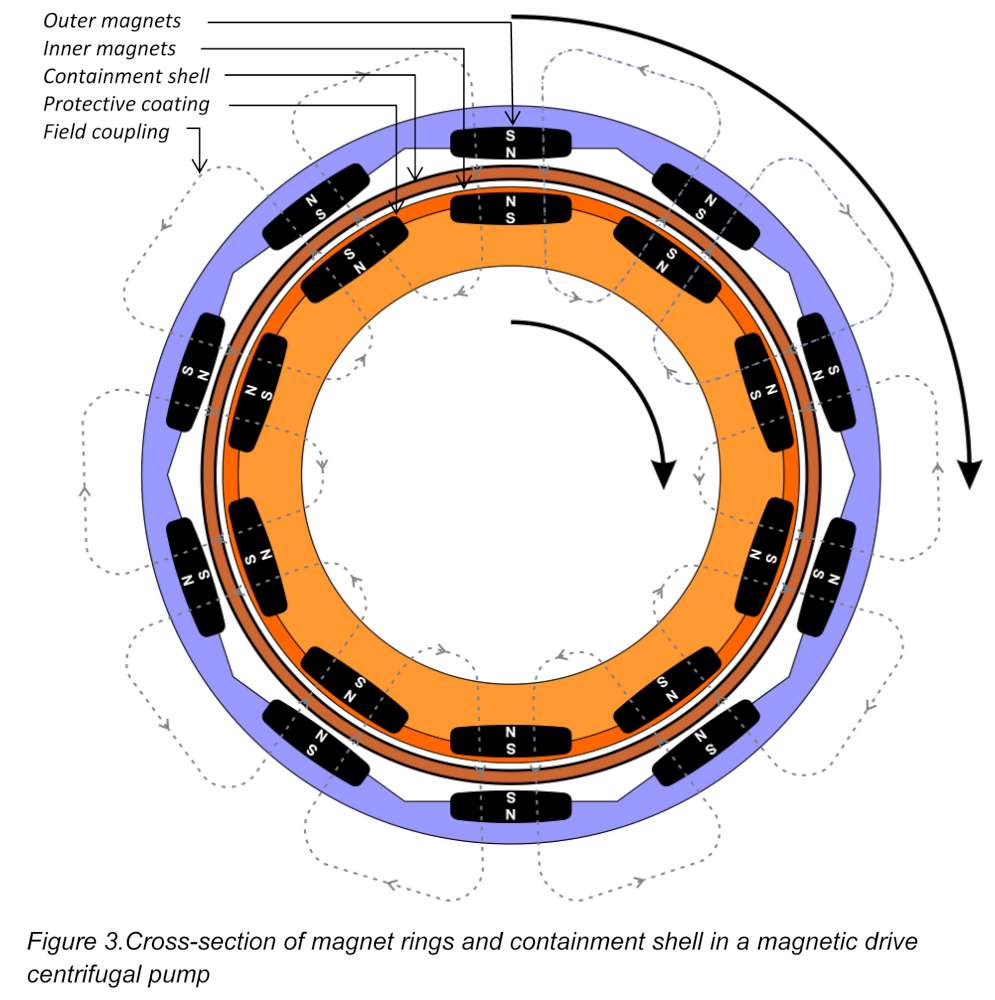
The maximum torque that can be achieved in a magnetic drive pump is determined by the gap between the magnets: the smaller the gap the larger the torque transfer. However, there is a limit to how small this can be engineered, since the gap must include the containment shell and any protective materials coating the magnets. For the safe operation of the pump, it is important that there is a reasonable gap between the rotating parts and the containment shell, especially if the pumped fluid is highly viscous or contains solids. All parts must therefore be machined to high tolerances for greatest efficiency. In addition to these engineering concerns, the material used in the construction of the containment shell is important in maintaining a high coupling efficiency between the two sets of magnets and in reducing power losses due to the generation of eddy currents.
The inner magnet ring, the pump shaft and its bearing are immersed in the pumped fluid and lubricated by it. It is important that these parts are designed to operate efficiently in the environment. With highly viscous liquids, friction losses can be high; in an abrasive or chemically aggressive medium, bearing wear can be a problem. However, with the right choice of wetted materials - including silicon carbide, thermoplastics, stainless steel and high nickel alloys - magnet drive pumps are ideal for handling aggressive, corrosive and hazardous liquids.
Magnetic drive pump or canned motor pump?
In a canned motor pump, the motor’s rotor winding is encapsulated in a ‘can’ and it, and the entire drive shaft up to the impeller is immersed in the pumped fluid (Figure 4).
Canned motor pumps tend to be smaller, have fewer bearings and can be more efficient. They also offer secondary containment as standard: if the ‘can’ is ruptured then the pumped medium is contained within the stator housing. This can be a particular advantage if the pumped medium is so dangerous or expensive that secondary containment is essential. Magnetic pump manufacturers offer secondary containment on some designs but this is usually an additional cost.
The main disadvantage of canned motor pumps is that a motor failure requires replacement of the whole unit. A magnetic drive pump can be repaired or upgraded because the motor is not an integral part of the pump. Both canned and magnetic drive pump designs have versions available to handle slurries, liquids at both high and low temperature, and volatile fluids.
Often, the choice of pump depends only on site standards or preferences.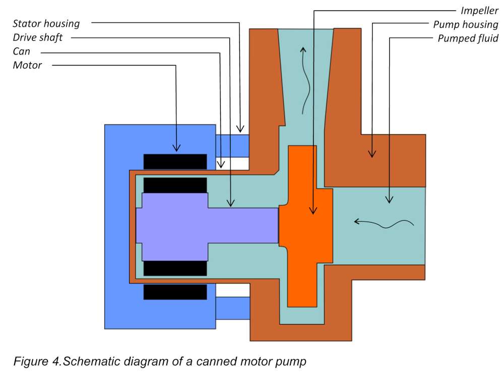
Summary
Advances in pump technology have enabled engineers to reduce the size of magnetic drive pumps whilst increasing their power and efficiency. Rare earth alloy magnets with high field strength allow compact design. New pump bearing designs and a wide range of wetted material options have enhanced pump lifetime, lowered power losses due to eddy currents and reduced maintenance downtime.
Different designs of magnetic drive pumps are available including centrifugal pumps, side channel pumps, turbine pumps, vane pumps and internal and external gear pumps. Magnetic drive pumps can be specified for applications where self-priming or handling solids or running dry is required and are often specified for pumping difficult liquids such as abrasive liquids, acids, bases, corrosives, flammables, inorganic solutions, liquids with entrained gases, organic liquids, slurries, solvents, toxic liquids, viscous and volatile liquids. Magnetic drive pumps are available for a wide range of viscosities at high and low temperatures at capacities from ml/hr to m³/min and for high system pressures and high differential pressures.
All these different designs of magnet drive pumps offer the key benefit of zero leakage of the pumped medium.
See our full range of pumps |
|---|
Send us your enquiry |
Contact us |